EMERSON – ASCO Solenoid Valve SCG356A466VMS 24/50, 3 Port, NC, 24V ac
- RS Stock No.:
- 488-609
- Mfr. Part No.:
- SCG356A466VMS 24/50
- Manufacturer:
- EMERSON – ASCO

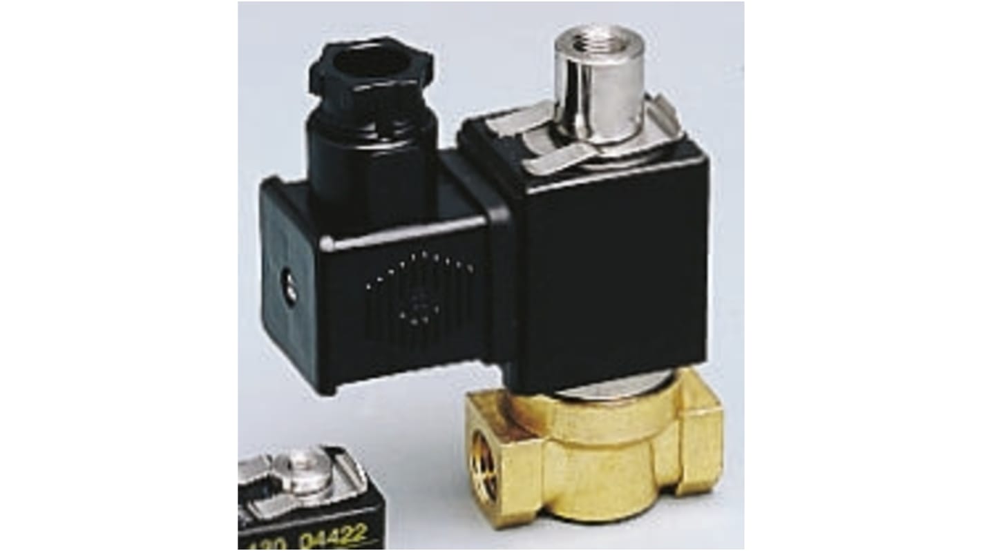
This image is representative of the product range
Unavailable
RS will no longer stock this product.
- RS Stock No.:
- 488-609
- Mfr. Part No.:
- SCG356A466VMS 24/50
- Manufacturer:
- EMERSON – ASCO
Specifications
Technical data sheets
Legislation and Compliance
Product Details
Find similar products by selecting one or more attributes.
Select all | Attribute | Value |
|---|---|---|
| Brand | EMERSON – ASCO | |
| Supply Voltage | 24V ac | |
| Product Type | Solenoid Valve | |
| Number of Ports | 3 | |
| Default Valve Position | NC | |
| Inlet Connection Type | Threaded | |
| Inlet Thread Standard | G ISO 228/1 | |
| Outlet Connection Type | Threaded | |
| Orifice Diameter | 1.6mm | |
| Application | Air, Inert Gas, Oil, Water | |
| Body Material | Brass | |
| Series | 356 | |
| Maximum Operating Pressure | 10 bar | |
| Minimum Operating Temperature | -10°C | |
| Outlet Thread Standard | G | |
| Maximum Operating Temperature | 60°C | |
| Standards/Approvals | DIN 43650, EN 175301-803, EN 60529, EC Directives, UL, CSA, IEC 335, ISO 4400 | |
| Hazardous Area Certification | ATEX, EC | |
| Maximum Opening Time | 10ms | |
| Flow Factor Kv | 0.08m³/h | |
| Maximum Closing Time | 10ms | |
| Select all | ||
|---|---|---|
Brand EMERSON – ASCO | ||
Supply Voltage 24V ac | ||
Product Type Solenoid Valve | ||
Number of Ports 3 | ||
Default Valve Position NC | ||
Inlet Connection Type Threaded | ||
Inlet Thread Standard G ISO 228/1 | ||
Outlet Connection Type Threaded | ||
Orifice Diameter 1.6mm | ||
Application Air, Inert Gas, Oil, Water | ||
Body Material Brass | ||
Series 356 | ||
Maximum Operating Pressure 10 bar | ||
Minimum Operating Temperature -10°C | ||
Outlet Thread Standard G | ||
Maximum Operating Temperature 60°C | ||
Standards/Approvals DIN 43650, EN 175301-803, EN 60529, EC Directives, UL, CSA, IEC 335, ISO 4400 | ||
Hazardous Area Certification ATEX, EC | ||
Maximum Opening Time 10ms | ||
Flow Factor Kv 0.08m³/h | ||
Maximum Closing Time 10ms | ||
RoHS Status: Exempt
Three-way, Zero Pressure, N/C Valves
Three-way solenoid valves with zero bar minimum operating pressure, normally closed with threaded port connection.
Brass body
Pressure not required for operation
Compact & lightweight
DIN plug connection
Ranging from -10°C to +100°C
Can be mounted in any position
3 Way Inert Gases and Fluid Valves
Compact solenoid valves suitable for most gas and fluid handling applications. Where practical, valves are shown with a schematic diagram showing the (circuit) function. The diagram is laid out so that the left hand side of the diagram describes the valves operation when the coil is energised. When the coil is de-energised, the spring (or servo-assist) return controls the valve and this is described on the right hand side of the diagram, see the typical schematic diagram below.,The 3//2-way designation indicates a valve with three ports and two modes of operation. It is normal practice to refer to 2//2-way valves as two-way.,The port designations A, B, P, P1, P2 and R are used on the schematic diagrams and are marked on the valve bodies. Valve bodies are marked for a specific circuit function but can often be used for other functions. Reference to the schematic diagrams and technical specifications will indicate the appropriate connections and pressure capabilities should an alternative circuit function be required.